
Following my PhD at McGill, I moved to LA to work in Dr. Dario Ringach’s lab at UCLA. We’ve been doing calcium imaging – GCamp6 – in mice via a custom-built microscope – you can read more about the microscope over at the Scanbox blog.
If you’re used to working with single electrodes or multi-unit arrays, calcium imaging will completely redefine your expectations of what neuroscience can be. You can get more than a hundred shiny neurons in a given field of view, so you can realistically ask and answer questions about how a local circuit works knowing that you’re not massively undersampling the population.
Inter-frame motion is an issue in awake behaving subjects. There are slow drifts and faster motions due to, e.g., grooming, which you need to correct for. Dario has a post on correcting for translation motion, which is dominant in slow drifts. During grooming, however, the motion can be fast enough that the field of view moves significantly during frame acquisition. Because the field of view is scanned from top to bottom – not captured all at once – this causes non-rigid deformations.
Specifically, vertical motion causes expansion and contraction of frames along the vertical axis, while horizontal motion causes shear. Of course, rigid motion dominates, so rigid motion compensation will be good enough for many analyses. However, if you’re interested in looking at correlations between neurons, for example, you will need to get rid of as much wide-field motion as you can. Wide-field variation will cause some parts of neurons to drop in or out of ROIs during motion, and those decreases or increases in fluorescence will tend to be correlated across ROIs, which is obviously a nightmare for correlational analysis.
There are a few ways of correcting for non-rigid motion; I had success with the method of Greenberg & Kerr (2009), which can correct for non-rigid motion with subpixel accuracy. It works on rigid-motion-corrected frames. Here’s a before and after during grooming:
 |
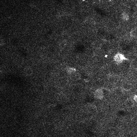 |
 |
| No compensation | Only rigid compensation | Non-rigid compensation |
Their method is based on the Lucas-Kanade method of optic flow estimation. You have a reference frame – T for template – and another image – I – you want to align it with. You do this by finding a displacement field D such that

By itself, this is a highly underconstrained problem. You use the usual trick of constraining the displacement fields to be a linear combination of basis functions, i.e.:

In our case, the 
Then you solve via least-squares–maximum likelihood under an assumption of Gaussian noise–for the weights of the basis function. The effect of the deformation field is first approximated via a first-order Taylor expansion. Then you use vanilla Gauss-Newton iterations until convergence.
It turns that with the choice of linear B-splines in the vertical direction a lot of the computations are quite simple, so it’s reasonably fast. Alignment of a frame might take a second, and most of that time is spent doing interpolation. You can speed things up a bit by using block-wise cross-correlation to get a guesstimate of the displacements.
A final question is what to use as a template. I use a 2-pass process. First, I use the mean fluorescence image for alignment. Then, I use a local temporal average of the fluorescence as the template. During grooming, the overall activity tends to increase, and some neurons which are usually not very active light up. These neurons are hard to align with the mean fluorescence image because they don’t really appear in there. Aligning them against where they were a few frames ago is easier.
Here’s some code to get you started:
function [Id,dpx,dpy] = doLucasKanade(T,I,dpx,dpy)
    warning('off','fastBSpline:nomex');
    Nbasis = 16;
    niter = 25;
    damping = 1;
    deltacorr = .0005;

    lambda = .0001*median(T(:))^2;
    %Use a non-iterative algo to get the initial displacement

    if nargin < 3
        [dpx,dpy] = doBlockAlignment(I,T,Nbasis);
        dpx = [dpx(1);(dpx(1:end-1)+dpx(2:end))/2;dpx(end)];
        dpy = [dpy(1);(dpy(1:end-1)+dpy(2:end))/2;dpy(end)];
    end
    %dpx = zeros(Nbasis+1,1);
    %dpy = zeros(Nbasis+1,1);

    %linear b-splines
    knots = linspace(1,size(T,1),Nbasis+1);
    knots = [knots(1)-(knots(2)-knots(1)),knots,knots(end)+(knots(end)-knots(end-1))];
    spl = fastBSpline(knots,knots(1:end-2));
    B = spl.getBasis((1:size(T,1))');

    %Find optimal image warp via Lucas Kanade

    Tnorm = T(:)-mean(T(:));
    Tnorm = Tnorm/sqrt(sum(Tnorm.^2));
    B = full(B);
    c0 = mycorr(I(:),Tnorm(:));

    %theI = gpuArray(eye(Nbasis+1)*lambda);
    theI = (eye(Nbasis+1)*lambda);

    Bi = B(:,1:end-1).*B(:,2:end);
    allBs = [B.^2,Bi];

    [xi,yi] = meshgrid(1:size(T,2),1:size(T,1));

    bl = quantile(I(:),.01);

    for ii = 1:niter

        %Displaced template
        Dx = repmat((B*dpx),1,size(T,2));
        Dy = repmat((B*dpy),1,size(T,2));

        Id = interp2(I,xi+Dx,yi+Dy,'linear');

        Id(isnan(Id)) = bl;

        c = mycorr(Id(:),Tnorm(:));

        if c - c0 < deltacorr && ii > 1
            break;
        end

        c0 = c;

        %gradient of template
        dTx = (Id(:,[1,3:end,end])-Id(:,[1,1:end-2,end]))/2;
        dTy = (Id([1,3:end,end],:)-Id([1,1:end-2,end],:))/2;

        del = T(:) - Id(:);

        %special trick for g (easy)
        gx = B'*sum(reshape(del,size(dTx)).*dTx,2);
        gy = B'*sum(reshape(del,size(dTx)).*dTy,2);

        %special trick for H - harder
        Hx = constructH(allBs'*sum(dTx.^2,2),size(B,2))+theI;
        Hy = constructH(allBs'*sum(dTy.^2,2),size(B,2))+theI;

        %{
        %Compare with fast method
        dTx_s = reshape(bsxfun(@times,reshape(B,size(B,1),1,size(B,2)),dTx),[numel(dTx),size(B,2)]);
        dTy_s = reshape(bsxfun(@times,reshape(B,size(B,1),1,size(B,2)),dTy),[numel(dTx),size(B,2)]);

        Hx = (doMult(dTx_s) + theI);
        Hy = (doMult(dTy_s) + theI);
        %}

        dpx_ = Hx\gx;
        dpy_ = Hy\gy;

        dpx = dpx + damping*dpx_;
        dpy = dpy + damping*dpy_;
    end
end

function thec = mycorr(A,B)
    A = A(:) - mean(A(:));
    A = A / sqrt(sum(A.^2));
    thec = A'*B;
end

function H2 = constructH(Hd,ns)
    H2d1 = Hd(1:ns)';
    H2d2 = [Hd(ns+1:end);0]';
    H2d3 = [0;Hd(ns+1:end)]';

    H2 = spdiags([H2d2;H2d1;H2d3]',-1:1,ns,ns);
end

function [dpx,dpy] = doBlockAlignment(T,I,nblocks)
    dpx = zeros(nblocks,1);
    dpy = zeros(nblocks,1);

    dr = 10;
    blocksize = size(T,1)/nblocks;

    [xi,yi] = meshgrid(1:size(T,2),1:blocksize);
    thecen = [size(T,2)/2+1,floor(blocksize/2+1)];
    mask = (xi-thecen(1)).^2+(yi-thecen(2)).^2< dr^2;

    for ii = 1:nblocks
        dy = (ii-1)*size(T,1)/nblocks;
        rg = (1:size(T,1)/nblocks) + dy;
        T_ = T(rg,:);
        I_ = I(rg,:);
        T_ = bsxfun(@minus,T_,mean(T_,1));
        I_ = bsxfun(@minus,I_,mean(I_,1));
        dx = fftshift(ifft2(fft2(T_).*conj(fft2(I_))));
        theM = dx.*mask;

        [yy,xx] = find(theM == max(theM(:)));

        dpx(ii) = (xx-thecen(1));
        dpy(ii) = (yy-thecen(2));
    end
end

4 responses to “Non-rigid deformation for calcium imaging frame alignment”
Thanks a lot, Patrick & David! This was _very_ useful. We had a lot of movement artefacts in our functional and structural dendritic spine imaging data (resonant scanning 2p) that rigid phase correlation registration did not take care of (in spite of running at 30 – 60 Hz). With the help of the old and sadly deprecated Accelereyes ML GPU toolbox (that’s still 2x faster than ML’s current implementation…) we can now LK register our data at ~15 frames/sec (512×512) with excellent results. The only issue I have is (inevitably) ‘squeezing’ of the background noise…
Here’s our implementation. The built in options are for regular and bidirectional raster scanning, though with the right inputs you can do free line scans as well.
https://www.dropbox.com/s/5c2cgvc4gg6jzm6/correct_scanned_imaging.m
We generally use piecewise linear functions in both x- and y. One thing that was noticed both by us and by Dombeck et al. is that in rodents, motion is greater along the rostrocaudal axis than the mediolateral. This, combined with the fact that it’s easier to correct motion along scan lines than across scan lines, means that scan lines are best run rostrocaudally.
It would be nice to put the original (uncorrected) movie too… for comparison.
Added. Here’s some higher res movies for presentations:
https://www.dropbox.com/sh/n27warbfvwa1s4k/AABkZgs2dNXuLiWwuNs4VNgBa