
In the last post, we wrote about people with bilateral vestibular damage (BVD), who sometimes call themselves wobblers. Quick recap: as a rare side effect of taking antibiotics in the aminoglycoside family, some people suffer ototoxicity, and lose vestibular function bilaterally. The vestibule is an organ that tracks one’s position in space, not unlike a the gyros and accelerometers in smartphones. Having lost their sense of equilibrium, people with BVD have difficulty standing and walking without falling down.
Their equilibrium can be recovered in the short term with sensory substitution. A stimulation device on their tongue feeds information equivalent to the vestibule’s; when they tilt their head to the left, they get a jolt on the left of their tongue; when they tilt forward, they get a jolt on the front of the tongue, and so on. After continuous usage over a period of months, neural plasticity kicks in, increasing the gain of other sensory modalities and recalibrating the residual signal in the damaged inner ear. As a consequence, they partially recover their sense of equilibrium even when not using the device.
Dr. Marissé Masis-Solano and I set about make a more practical version of this system, using off-the-shelf open electronics. This was our first large project with open-source electronics, and we learned a lot about how important it is to iterate quickly to find the design pain points. Here’s how we made our prototype.
The premise
Our basic idea was to attach a measurement device to a person’s head to measure its tilt; to relay that information via RF to another device on the person’s body; and to actuate haptics using a receiver device so the tilt could be felt through another sense.
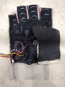
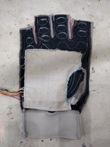
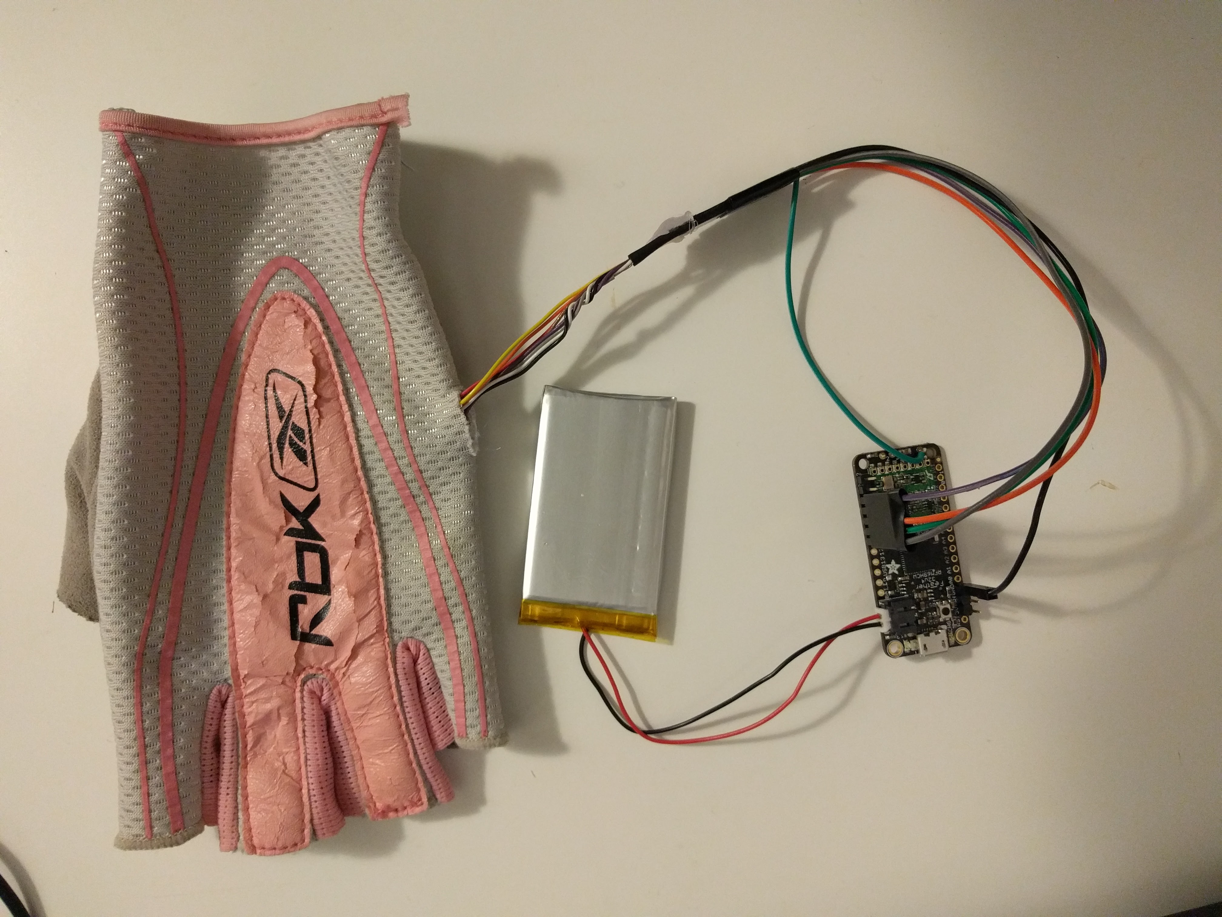
The glove
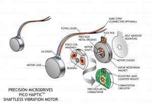
We decided to build a glove to house haptics. The haptics information would be relayed via vibration motors. ERM motors — eccentric rotating mass motors — are DC motors with an eccentric mass, which makes them vibrate when applying a DC current; it’s the same kind of device that makes your smartphone vibrate.
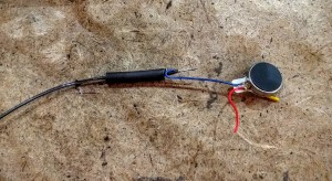
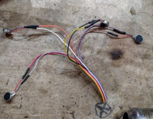
I assembled 4 ERM motors into an array with some solder, shrink-wrap and a bit of hot glue. Marissé then sewed into a glove via a reinforced flap. Fun fact: Marissé is a talented eye surgeon, and as a consequence, she can sew, but she can only sew with curved needles; thankfully, there were a few of those lying around at NoiseBridge.
The headpiece
Next, we scoped out the headpiece. We had originally intended to use a simple analog accelerometer to measure the vector of gravity, but in our initial tests it was tricky to reliably calibrate, and didn’t provide the resolution we needed for our experiments.
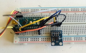
We decided to upgrade to a BNO055 9-DOF, a board which integrates an accelerometer, a gyro, as well as a compass to measure the 9 different vector components of absolute spatial orientation. An IC on the board does Kalman filtering to reliably output absolute orientation, and has its own on-board calibration routines, as well as means of loading previous calibrations.
At 30$, it’s one of the most expensive components in the whole design. That being said, a comparable device could easily have run into the thousands of dollars only a few years ago — smartphones have made 9-DOFs big business, and prices have fallen steadily.
The cheap accelerometers still have their uses, however; we used one to take some measurements of the impulse response function of the coin ERMs when applying a DC current.
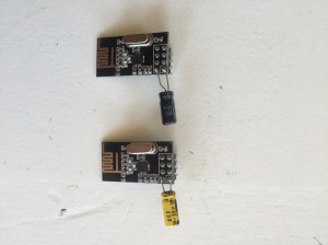
We originally experimented with sending the signal from the headpiece of the receiver via standalone Nordic radio boards. However, we found that the combined size of a radio, a 9-dof plus the microcontroller was a little unwieldy. Therefore, we switched over to a microcontroller with integrated RF capabilities.
I bought a couple of Adafruit’s Bluefruit LE Arduino-compatible boards, but quickly found out that they weren’t appropriate for our project, as they don’t support peer-to-peer communication. So I ordered a couple of 32u4 with RFM69 radios, which have the exact same form factor as the Bluefruit, but instead communicate via an ad-hoc RF protocol.
A big advantage of this line of microcontrollers is that they are directly compatible with LiON battery packs, which can be found in a large range of form factors.
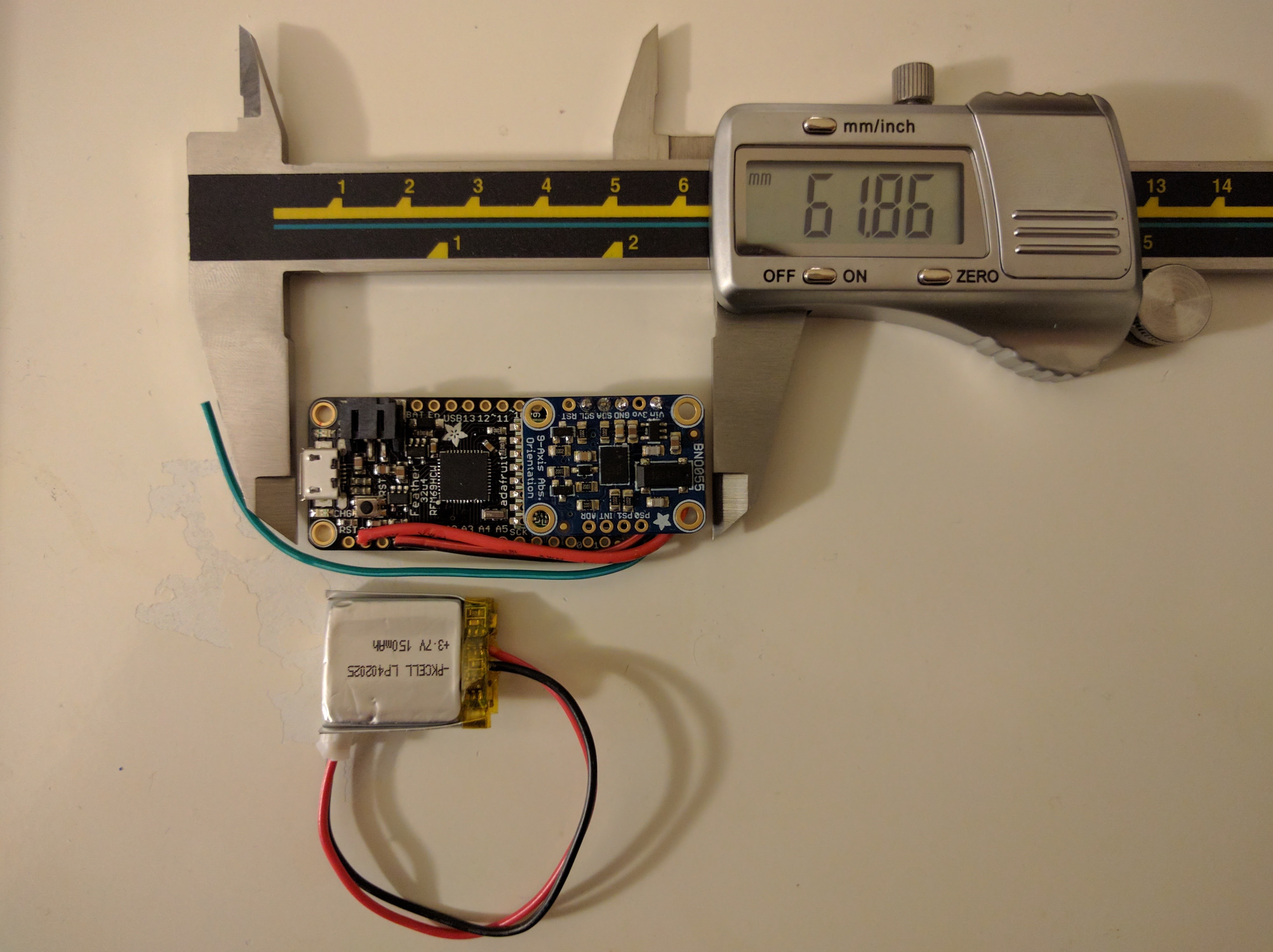
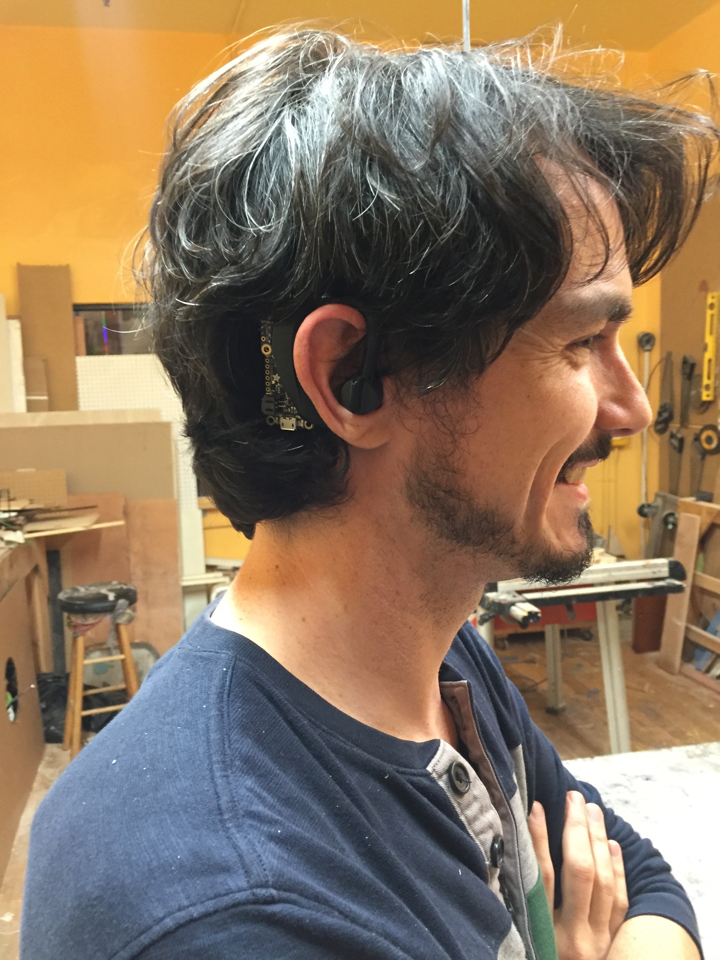
A bit of soldering later, we had our prototype headpiece. Originally, we had planned to keep it simple, and put the assembly inside of giant earmuffs, the kind that construction workers use to drill asphalt without suffering hearing loss. However, at that point, the whole assembly was so small that it seemed feasible to attach it directly to an ear.
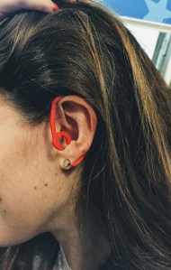
We 3D printed a couple of different ear hooks we found on thingiverse, but nothing was very satisfactory.
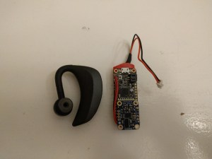
Then we struck gold at NoiseBridge: in the random discarded electronics bin, we found an old Bluetooth headset! We gutted the old electronics, and our assembly fit perfectly within the shell of the old headset.
Initial tests and adjustments
We started out with a second 32u4 Arduino device as the sole component of the receiver, directly controlling the ERM vibration motors. The headpiece would continuously transmit its position in space, and the receiver would transduce that information to vibration on the palm. You would tilt your head to the right, and the ERM motor in the right part of the glove would vibrate.
Several things became immediately apparent:
- Calibrating the headpiece was clunky; you needed to plug in the headpiece to a computer via USB and enter a series of commands in the Arduino serial monitor to set the zero point of the accelerometer.
- Understanding the status of the receiver — whether it was receiving RF input or not, and whether that input was calibrated or not — was difficult because it didn’t have any way of showing its status beyond flashing a single red LED.
- You couldn’t really feel the vibration of the ERM motors within the glove.
We went back to the drawing board and made a series of modifications to solve each of these three problems.
First, we worked on the calibration. We originally used 4-point calibration — the user was instructed to tilt their head forward, backward, left, right and then the headpiece would send calibrated information to the receiver. We got that down to two-point calibration: a simpler sequence in which the user was instructed to keep their head at a neutral position, and then move forward.
The was enough to measure the location of the gravity vector in the neutral position, as well as an orthogonal vector corresponding to the forward direction; their cross-product gave the third axis, corresponding to tilt towards the right. Arduinos have very little memory, so I had to come up with a means of measuring the variance of the measurements online to make sure that the calibrations were accurate. I used Welford’s algorithm to measure the variance of the 9-dof measurements online in each of the two calibration positions, rejecting calibrations that were too noisy.
This calibration procedure still required the user to plug the headpiece into the USB, so I made some modifications to allow the calibration sequence to be started from the receiver. I added a capacitive touch board to add a few flexible buttons to the glove, and an RGB LED to tell the user the status of the device: green for calibrated, red for uncalibrated, or blue for mid-calibration.
Because the calibration was now triggered from the receiver, I had to set up bidirectional communication between the receiver and the headpiece. The Arduino IDE is not well-adapted to this kind of multiple device project, so I upgraded to PlatformIO. See my previous post on PlatformIO on how to set up a multi-Arduino project.
To get better haptic feedback from the glove, I decided to use a booster circuit. The 32u4 uses 3.3 volt logic, while the coin ERM motors support up to 5V; I figured that by increasing the voltage, it should be possible to get a stronger vibration, which would be easier to feel. I re-used the same logic transistor logic that I has used previously in the flicker fusion project to boost the ERM devices up to 4.2V.
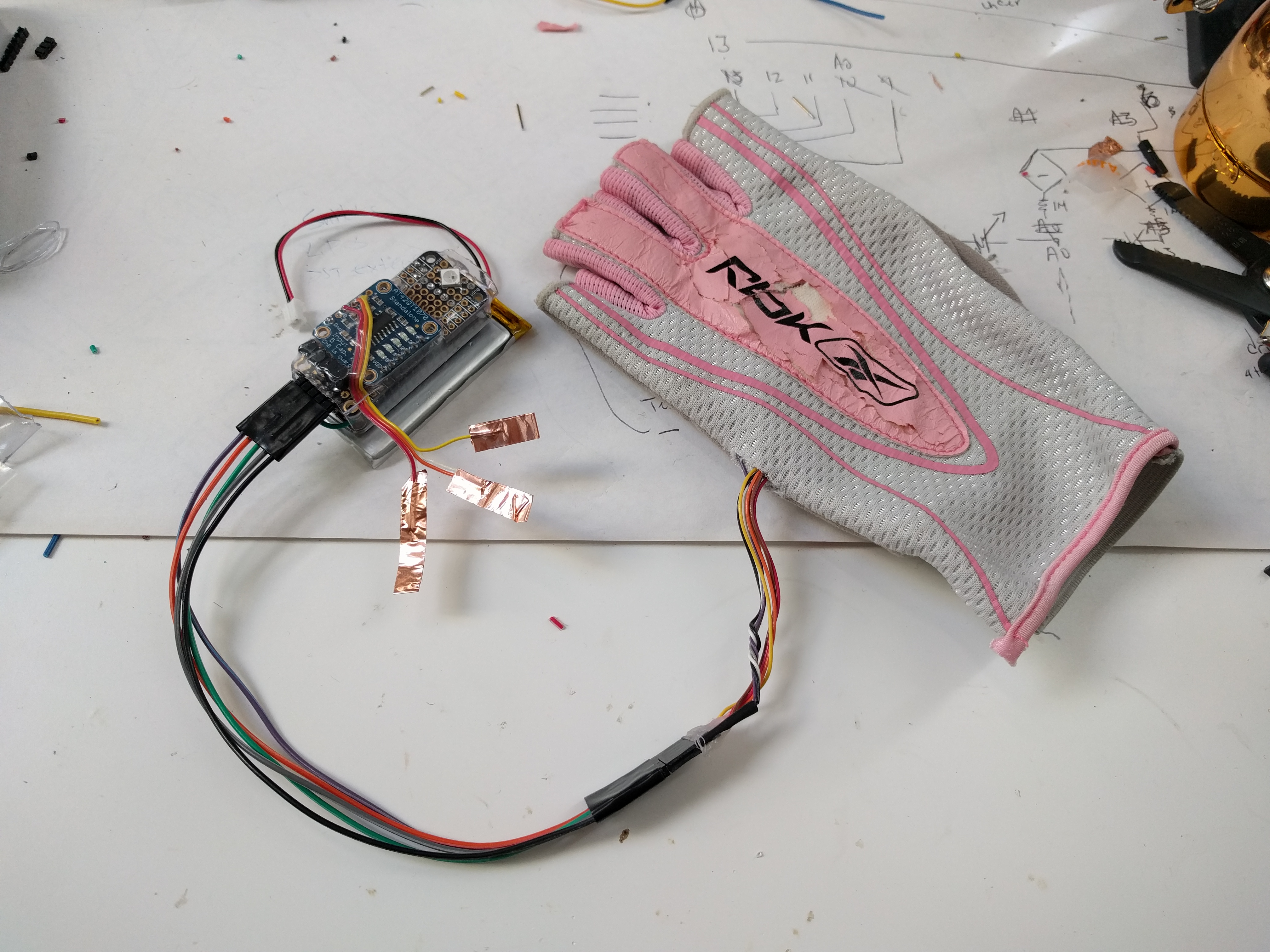
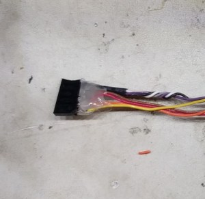
The whole thing, with three stacked boards, was a little fragile, and it was easy to accidentally touch the GPIO pins; I placed the whole thing in transparent shrink tube, and after applying heat, got a nice, solid build. Here’s the code to make it all work.
Prototype
So how does it work? The headpiece is comfortable and accurately transmits tilt information after a straightforward calibration procedure; RF communication is seamless, and there’s scarcely any sync issues; LED feedback from the receiver is easy to understand.
However, we found that, even after boosting the ERM motor drive, we couldn’t properly perceive the location of the vibration within the glove. Was it that the palm was not sensitive enough to vibration? Did we use the wrong stimulation sequence? We tried, haphazardly, to fix the problem using different stimulation protocols, adjusting the strength of the stimulation, and so forth, but we got stuck for a while.
Part of the reason we got stuck is that we had a lot of opinions — do you think this works better than the last version? — but not a lot of data — is this quantitatively better than the last version?. The answer was right under our nose — psychophysics! We needed to measure how different stimulation parameters influenced our perception, and optimize them until we got something that worked.
In the next post, I’ll show how we used psychophysics to pinpoint exactly how we could tweak our design to make it work. Follow me on Twitter or Facebook to get notified of next week’s installment.
